Application of Lingchen Technology Longmen Control Platform, Flexible Return and Positioning Accuracy Compensation Function
There are many control methods for the gantry, and the common ones are as follows: single feedback, single motor; Single feedback, multiple motors; Master slave control; Cross decoupling algorithm, etc.
1、 Lingchen Technology Longmen Control Platform Solution
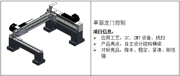
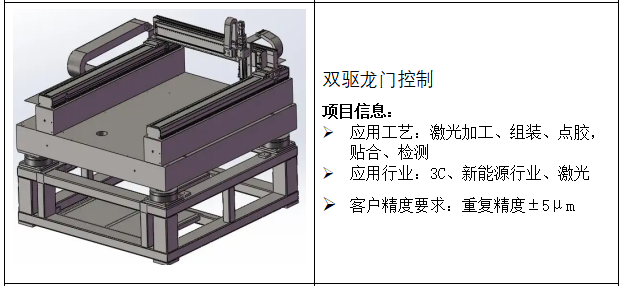

Figure 1: Non standard Customization of Lingchen Technology's Dual Drive Longmen Platform (Image sourced from the internet)
2、 There are many control methods for the gantry, with the following common ones:
Single feedback, single motor: Only one side is powered by a motor, while the other side is supported by a guide rail and moves through mechanical stress. This method is relatively economical and suitable for applications with low speed, small span, light load, and low accuracy requirements.
Single feedback, multiple motors: equivalent to connecting two motors in parallel, with a set of control signals controlling both motors simultaneously. This method is relatively simple to control, but due to the difficulty in ensuring consistency between the machinery and the motor, the current loop control accuracy of the two motors is poor, resulting in uneven thrust and poor control performance.
Master slave control: Lingchen Technology's gantry control adopts a high-performance driver with built-in gantry algorithm. The master slave uses 10M high-speed communication to generate current control signals to synchronize the two Y1 and Y2 axes, and monitors the position deviation between the master and slave axes in real-time for dynamic adjustment. It can achieve average load distribution between the master and slave axes. Coupled with Lingchen's self-developed high-precision gantry platform, it can have higher speed, acceleration, and positioning accuracy Repetitive positioning accuracy, straightness, orthogonality.

Figure: 2: Schematic diagram of the master-slave control gantry algorithm principle
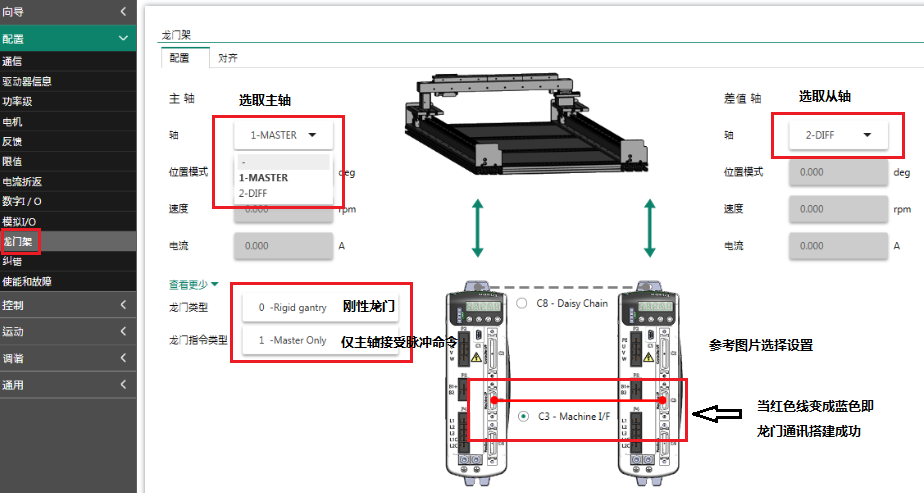
Figure 3: Master Slave Gantry Control Configuration Interface
Cross decoupling algorithm: The high-precision gantry dual drive platform of Lingchen Technology adopts a unique cross decoupling control algorithm to control the Gantry direction axis and Yaw torsion pendulum axis as two control objects, rather than controlling two separate motors, reducing the impact of coupling. This method can maximize control performance. Paired with Lingchen's self-developed high-precision gantry platform, it can have higher speed, acceleration, positioning accuracy, repeated positioning accuracy, straightness, and orthogonality.
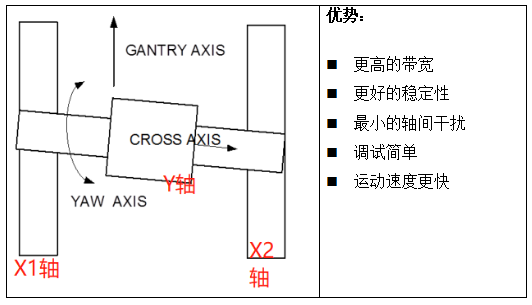
Figure: 4: Schematic diagram of cross decoupling gantry control principle
2、 Flexible return to zero
Background:
In the rigid gantry mode of the device, follow the following steps to test the accuracy of the return to zero repetition through camera capture.
Test steps: enable the gantry to break - push it once - enable the gantry to go up - take a photo after returning to zero. (All other axes are enabled to remain stationary, only the gantry axis is moved).
Test results: The repeated positioning error of several times of testing can reach 40-50um.
Reason analysis: The rigid gantry algorithm requires the equipment to have absolute rigidity, especially for some cases where the span is relatively large and the crossbeam is heavy, which is not absolute rigidity. Every time the gantry is disabled, especially when it is disabled, it will deform and cause changes in the attitude of the shaft system after being pushed by hand. However, the traditional rigid gantry algorithm returns to zero by independently controlling the main axis to find the index score line. The secondary axis has no power and relies on the mechanical rigidity of the system crossbeam to synchronize with the main axis. This is limited by the system's mechanical rigidity, which cannot adjust the position to ensure consistency after each return to zero. Therefore, there is a problem of repeatability in returning to zero.
Flexibility principle: When using a driver to return to zero, both the master and slave axes need to be equipped with index points, and the distance between the two indices needs to be calculated in advance, gantryoffset, and set on the slave axis.
The gantry performs the following zero return process:
Find the spindle index---
Find the slave axis index---
Alignment and offset settings and calibration---
The spindle returns to the original position in the homing mode to find the index - the homing is completed.
At this time, the driver will also calculate the position Calc of the slave shaft internally and calculate the difference Err with the gantryoffset. During the return to zero process, when returning to the spindle index for the second time, the difference Err will be added to ensure that the relative position of the master and slave shafts is consistent each time.
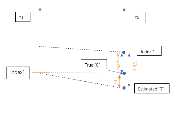
Figure 5: Flexible gantry return to zero principle operation
Flexible gantry calibration mode, bias, calibration function activation

Figure 6: Enabling gantryoffset
Result: After setting it as a flexible gantry, the zero return accuracy was tested according to the above steps. The actual position of the master and slave shaft motors fluctuated within 3um (which can be viewed by inputting MFBRAW through the terminal), and the camera's photography accuracy was within 5um, meeting customer requirements.
3、 Position error compensation
When applied in high-precision situations, we often encounter problems with the positioning accuracy of the system, resulting in the system being unable to operate according to customer requirements with precision. Therefore, customers have doubts about the accuracy of the equipment. This accuracy error is caused by the following aspects:
Abbe Error
Environmental temperature impact
Cosine error
Dead range error
The existence of these errors cannot be eliminated without compensation and correction. They can be directly measured using a laser interferometer, and the actual position error data after measurement can be directly imported into the built-in error compensation table of the driver.
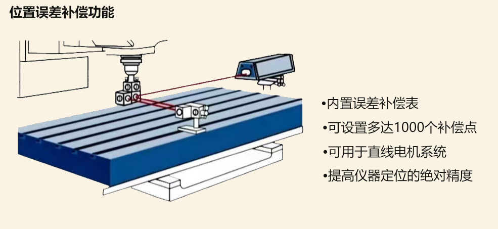
Figure 7 Internal position error compensation function of servo driver
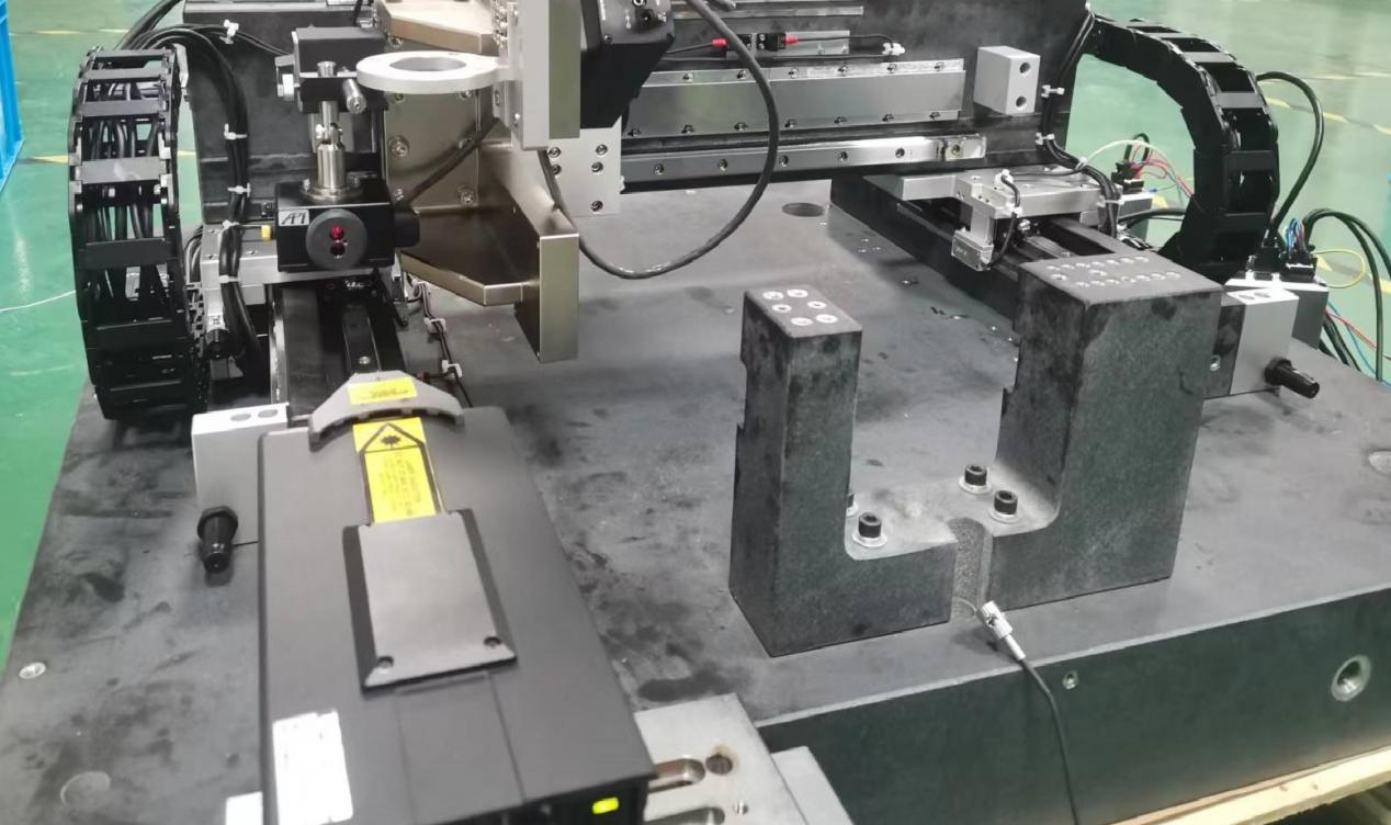
Figure 8 Measurement of positioning accuracy of linear motor system using laser interferometer
Import position error compensation file into servo driver
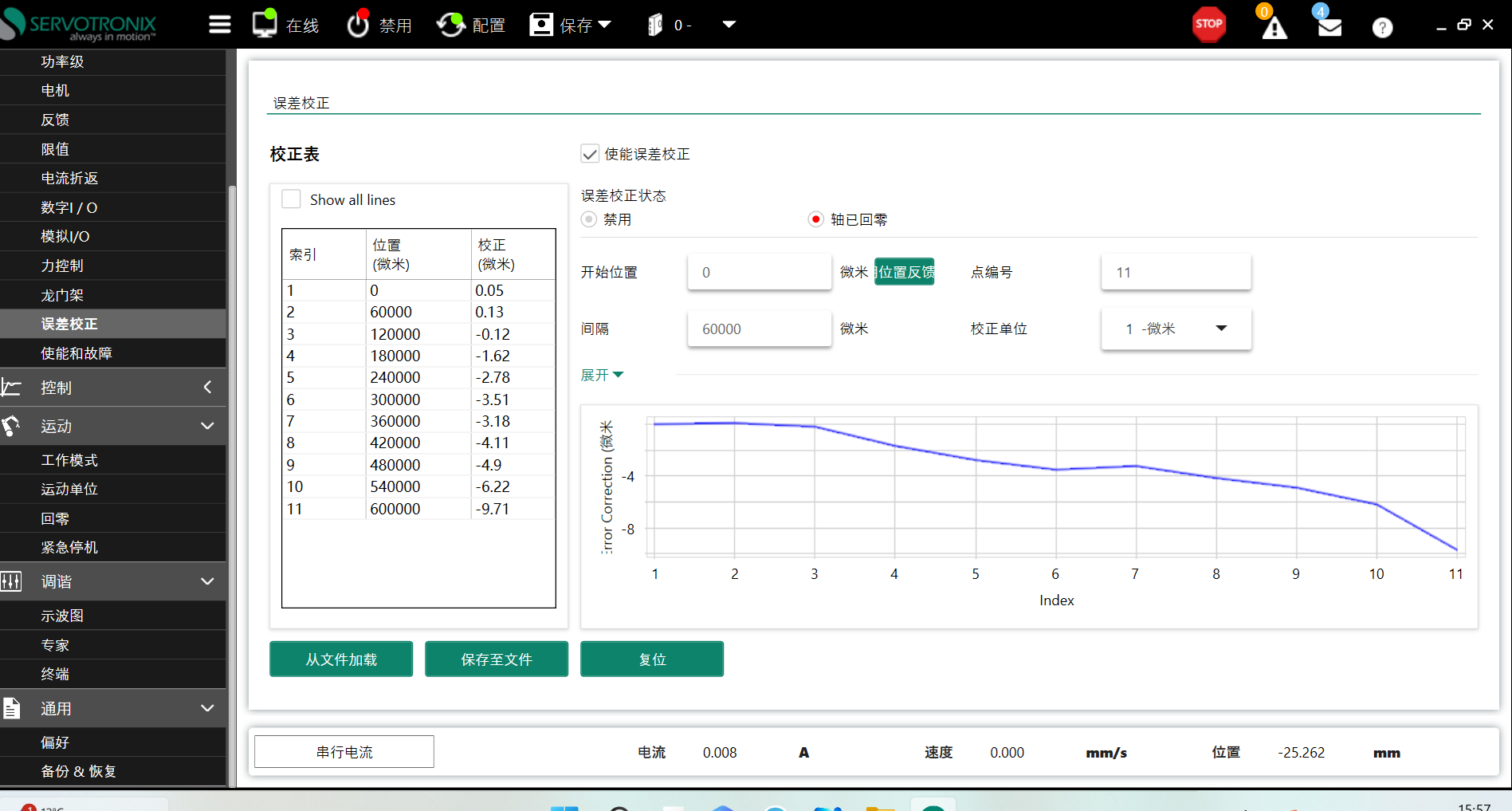
Figure 9 Internal Position Error Compensation Table of Servo Driver
Interferometer measurement of linear motor system, comparison of position accuracy before and after compensation:
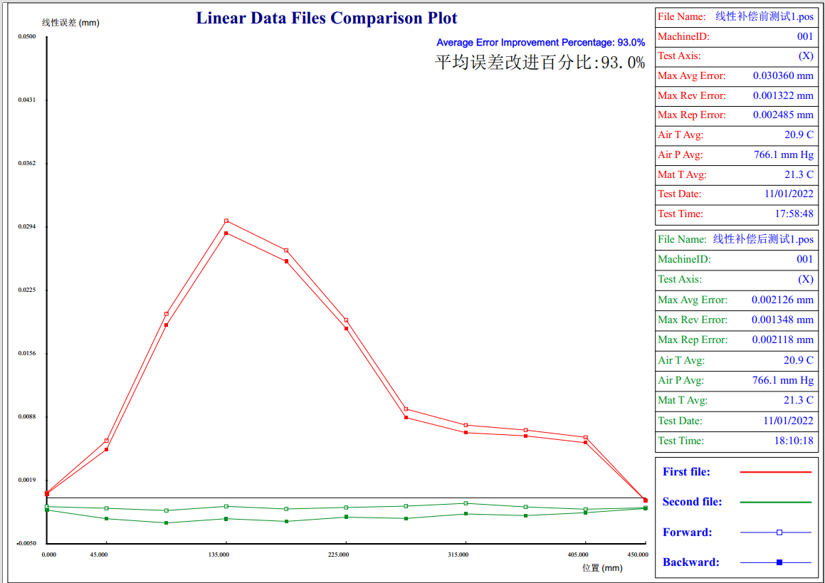
Figure 10 Interferometer Accuracy Measurement Position Accuracy Report
The average positioning deviation obtained before compensation using a laser interferometer is 0.030360mm. (Red in the picture)
Laser interferometer measurement, after compensation, can obtain an average positioning deviation of 0.002126mm. (Green in the picture)
龙门控制平台,直线电机控制平台


